Microchip Pic32Cm Mc Microcontroller For Power Electronics
Microchip Pic32Cm Mc Microcontroller For Power Electronics
Published 10/2024
MP4 | Video: h264, 1920x1080 | Audio: AAC, 44.1 KHz
Language: English | Size: 11.83 GB | Duration: 18h 21m
Examples for power electronics applications using the Curiosity Nano Evaluation Kit
What you'll learn
Architecture of the PIC32CM1216MC00032 microcontroller
Installing MPLAB X IDE and other SDK
Understanding project setup and libraries
Overview of the peripherals used in power electronics applications
Using GPIO pins through the PORT peripheral
Configuring and setting up interrupts and Interrupt Service Routines (ISR)
Using timers through the Timer Counter (TC) module
Generating PWM pulses through the Timer Counter for Control (TCC) module
Using the Analog to Digital Converter (ADC) for measured signals and control implementation
Using the Event System Module
Requirements
C programming
Basics of data structures and types for embedded systems
Recommended: Microcontroller programming for power electronics engineers (Using the Texas Instruments TMS320F28069 kit)
Description
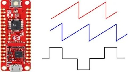
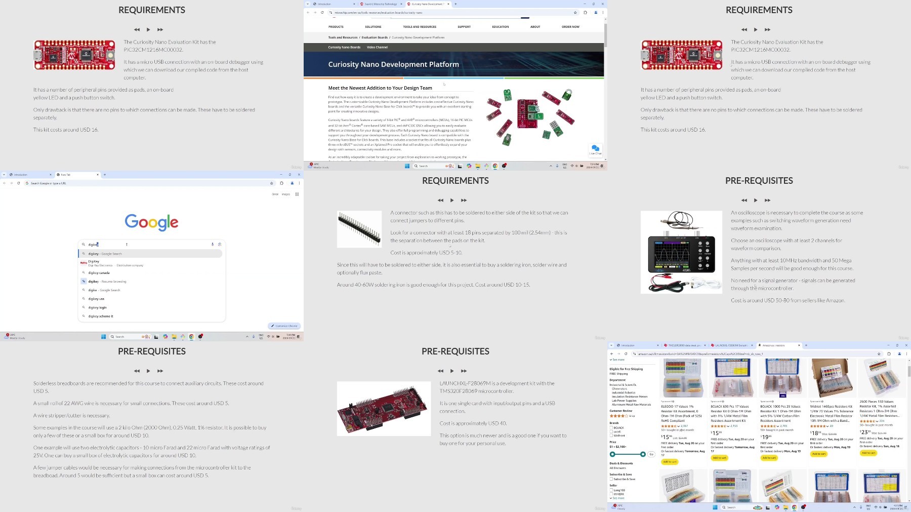
The course will describe how to use the PIC32CM1216MC00032 microcontroller from Microchip for power electronics applications. The PIC32CM MC microcontroller is a very popular low-cost microcontroller used in the power industry for various applications such as motor control and power factor correction. The purpose of this course is to provide young engineers with exposure to microcontrollers used in industry, and help them land their first jobs as power electronics engineers or firmware engineers. The course can also be used as training material by companies to train their engineers in using PIC32 microcontrollers from Microchip. The course covers both theory and programming, with details on the architecture of the microcontroller and its peripherals, as well as code sessions where projects are built from the ground up. The projects are accompanied by experiments with the results being observable either through blinking LEDs or through waveforms on the oscilloscope.The course describes how students can setup a low-cost electronics lab with components available from online marketplaces. The microcontroller kit (Curiosity Nano Evaluation Kit) needed for the course is readily available in many online marketplaces and costs merely USD 16. The course will begin with very simple examples such as how to make LEDs glow and flash. The course will then progress towards generating Pulse Width Modulation (PWM) gating signals and using the Analog to Digital Converter (ADC) for closed-loop control. The course will use the MPLAB X IDE and the MPLAB XC32 compiler provided for free by Microchip, and also example projects and starter files available on the Microchip website and GitHub page. The course will describe how necessary software can be downloaded and how the student can interpret and understand the example projects.
Overview
Section 1: Introduction
Lecture 1 Welcome
Lecture 2 Target audience of the course
Lecture 3 Hardware requirements of the course
Lecture 4 Software requirements of the course
Lecture 5 Tips for completing the course
Section 2: System Setup
Lecture 6 Introduction
Lecture 7 Installing MPLAB X IDE and MPLAB XC32 compiler
Lecture 8 Downloading the starter project for the Curiosity Nano Evaluation Kit
Lecture 9 Microchip GitHub project repository
Lecture 10 Testing the evaluation kit with the starter project
Lecture 11 Project files and directories
Lecture 12 Technical documentation
Lecture 13 Tips for electronics
Section 3: Microcontroller architecture and GPIO (PORT) module programming
Lecture 14 Introduction
Lecture 15 Basics of microcontroller architecture
Lecture 16 GPIO pins and peripheral functionalities
Lecture 17 Setting up the PORT module (GPIO) project
Lecture 18 PORT registers
Lecture 19 Reading header files for PORT register configurations
Lecture 20 Reading PORT initialization function - part 1
Lecture 21 Reading PORT initialization function - part 2
Lecture 22 Cleaning up the base starter project
Lecture 23 Connecting LEDs to GPIO pins of evaluation kit
Lecture 24 Updating code for new project specifications - driving LEDs
Lecture 25 Compiling the project
Lecture 26 Executing the project
Lecture 27 Conclusions
Section 4: Timers
Lecture 28 Introduction
Lecture 29 Overview of timing
Lecture 30 Setting up the 48MHz on-board oscillator
Lecture 31 Setting up the 32.768kHz on-board oscillator
Lecture 32 Setting up Generic Clock Generators
Lecture 33 Setting up the Main Clock Generator
Lecture 34 Configuring the Timer Counter (TC) module
Lecture 35 Interrupt Vector Table
Lecture 36 Choosing an example project from GitHub
Lecture 37 Understanding example project code - part 1
Lecture 38 Understanding example project code - part 2
Lecture 39 Understanding example project code - part 3
Lecture 40 Setting up new project
Lecture 41 Correction on copying source file code
Lecture 42 Rewriting project - part 1
Lecture 43 Rewriting project (setting up 48MHz oscillator) - part 2
Lecture 44 Rewriting project (setting up 32kHz oscillator) - part 3
Lecture 45 Rewriting project (setting up GCLK Generators) - part 4
Lecture 46 Rewriting project (enabling peripheral channels) - part 5
Lecture 47 Rewriting project (main clock generator) - part 6
Lecture 48 Rewriting project (expand TC module library) - part 7
Lecture 49 Rewriting project (updating control register) - part 8
Lecture 50 Rewriting project (completing config of TC0 module) - part 9
Lecture 51 Rewriting project (duplicating config for TC3 module) - part 10
Lecture 52 Rewriting project (setting up timer interrupts) - part 11
Lecture 53 Rewriting project (update interrupt vector table) - part 12
Lecture 54 Rewriting project (enabling timers and toggling GPIO pins) - part 13
Lecture 55 Compiling the project
Lecture 56 Executing the timer project
Lecture 57 Conclusions
Section 5: Timer Counter for Control (TCC) - Pulse Width Generation Module
Lecture 58 Introduction
Lecture 59 Overview of the TCC module
Lecture 60 Waveform Generator
Lecture 61 Output matrix
Lecture 62 Interrupts
Lecture 63 Control and status registers
Lecture 64 Example TCC project from GitHub
Lecture 65 Expanding GPIO project to include TCC library files
Lecture 66 Choosing GPIO pins as TCC Waveform Output (WO) pins
Lecture 67 Configuring TCC WO pins
Lecture 68 Configuring clocks
Lecture 69 Resetting the TCC0 module and choosing the clock prescaler
Lecture 70 Choosing the waveform generator
Lecture 71 Setting the PWM cycle period
Lecture 72 Waiting for period register to synchronize
Lecture 73 Writing ISR for the TCC0 interrupt
Lecture 74 Updating the interrupt vector table
Lecture 75 Enabling/starting the TCC module
Lecture 76 Compiling the project
Lecture 77 Executing the project to view basic gating signals
Lecture 78 Inverting the gate pulses at output pins
Lecture 79 Executing project - complementary waveforms with pins inverted
Lecture 80 Dead-time insertion
Lecture 81 Configuring dead-time using WEXCTRL register
Lecture 82 Executing project - dead-time inserted between complementary pulses
Lecture 83 Conclusions
Section 6: Analog to Digital Converter (ADC)
Lecture 84 Introduction
Lecture 85 Overview of the ADC module
Lecture 86 Control and setup of the ADC module
Lecture 87 Configuring the analog input channels
Lecture 88 Completion of the ADC process
Lecture 89 Generating mock analog signals for testing
Lecture 90 Setting up the ADC project
Lecture 91 Choosing the analog input pins in the project
Lecture 92 Including Timer Counter (TC) modules for generating test signals
Lecture 93 Initializing the timer counter module
Lecture 94 Configuring the timer counter module
Lecture 95 Setting up interrupts for the timer counter module
Lecture 96 Generating rectangular waveforms for test signals
Lecture 97 Executing project - verifying analog test signals
Lecture 98 Including ADC in the project
Lecture 99 Choosing the analog inputs
Lecture 100 Updating clocks to include ADC
Lecture 101 Setting prescaler for ADC clock
Lecture 102 Calibrating the ADC module
Lecture 103 Configuring the analog input channels
Lecture 104 Enabling the ADC interrupt
Lecture 105 Updating interrupt vector table
Lecture 106 Enabling the ADC module and issuing SOC trigger
Lecture 107 Extracting converted values in the ISR
Lecture 108 Using the converted values to compute the original signals
Lecture 109 Verification of the conversion process
Lecture 110 Compiling the project
Lecture 111 Setting ADC reference
Lecture 112 Executing project - verifying sawtooth waveform thresholds
Lecture 113 Event System Module Overview
Lecture 114 Setting up the Event System Module
Lecture 115 Starting the Event System example project
Lecture 116 Updating the clocks to include the Event Systems module
Lecture 117 Setting the Event System configuration registers
Lecture 118 Updating configuration of TCC0 module for event generation
Lecture 119 Updating configuration of ADC0 module for event generation
Lecture 120 Compiling the project
Lecture 121 Executing the project - verifying the results
Lecture 122 Conclusions
Section 7: Conclusions
Lecture 123 Conclusions
Undergraduate students in electrical engineering,Early level graduate students in electrical engineering,Firmware and test engineers
https://ddownload.com/8u0oj3loct3u/Udemy_Microchip_PIC32CM_MC_microcontroller_for_power_electronics_2024-9.part1.rar
https://ddownload.com/2dnydppmr395/Udemy_Microchip_PIC32CM_MC_microcontroller_for_power_electronics_2024-9.part2.rar
https://ddownload.com/3zrfqj1a5rta/Udemy_Microchip_PIC32CM_MC_microcontroller_for_power_electronics_2024-9.part3.rar
https://ddownload.com/kqkcl5o0sh8p/Udemy_Microchip_PIC32CM_MC_microcontroller_for_power_electronics_2024-9.part4.rar
https://ddownload.com/yfoiel10ncw3/Udemy_Microchip_PIC32CM_MC_microcontroller_for_power_electronics_2024-9.part5.rar
https://ddownload.com/99jlni5ibqzb/Udemy_Microchip_PIC32CM_MC_microcontroller_for_power_electronics_2024-9.part6.rar
https://rapidgator.net/file/4217c662a096f577469ed1fa99c1e8ae/Udemy_Microchip_PIC32CM_MC_microcontroller_for_power_electronics_2024-9.part1.rar
https://rapidgator.net/file/e5ff754e81c8db84569f21e232beea0e/Udemy_Microchip_PIC32CM_MC_microcontroller_for_power_electronics_2024-9.part2.rar
https://rapidgator.net/file/d50d7b87b3778cbb4a4a777fc93c63a1/Udemy_Microchip_PIC32CM_MC_microcontroller_for_power_electronics_2024-9.part3.rar
https://rapidgator.net/file/681c299a9cbe172b7463a23344c17a45/Udemy_Microchip_PIC32CM_MC_microcontroller_for_power_electronics_2024-9.part4.rar
https://rapidgator.net/file/aa60316f1c4f89d6aa0ea1b1356e285d/Udemy_Microchip_PIC32CM_MC_microcontroller_for_power_electronics_2024-9.part5.rar
https://rapidgator.net/file/077eb5d1cdd1f03c6dabbae998774b3b/Udemy_Microchip_PIC32CM_MC_microcontroller_for_power_electronics_2024-9.part6.rar
https://turbobit.net/jwevrjztcit0/Udemy_Microchip_PIC32CM_MC_microcontroller_for_power_electronics_2024-9.part1.rar.html
https://turbobit.net/w1xl4lxz8p6l/Udemy_Microchip_PIC32CM_MC_microcontroller_for_power_electronics_2024-9.part2.rar.html
https://turbobit.net/hpj425fuknng/Udemy_Microchip_PIC32CM_MC_microcontroller_for_power_electronics_2024-9.part3.rar.html
https://turbobit.net/716f7ou04l7l/Udemy_Microchip_PIC32CM_MC_microcontroller_for_power_electronics_2024-9.part4.rar.html
https://turbobit.net/ixb8ltpl56k5/Udemy_Microchip_PIC32CM_MC_microcontroller_for_power_electronics_2024-9.part5.rar.html
https://turbobit.net/o1lb62oup9b5/Udemy_Microchip_PIC32CM_MC_microcontroller_for_power_electronics_2024-9.part6.rar.html
What you'll learn
Architecture of the PIC32CM1216MC00032 microcontroller
Installing MPLAB X IDE and other SDK
Understanding project setup and libraries
Overview of the peripherals used in power electronics applications
Using GPIO pins through the PORT peripheral
Configuring and setting up interrupts and Interrupt Service Routines (ISR)
Using timers through the Timer Counter (TC) module
Generating PWM pulses through the Timer Counter for Control (TCC) module
Using the Analog to Digital Converter (ADC) for measured signals and control implementation
Using the Event System Module
Requirements
C programming
Basics of data structures and types for embedded systems
Recommended: Microcontroller programming for power electronics engineers (Using the Texas Instruments TMS320F28069 kit)
Description
The course will describe how to use the PIC32CM1216MC00032 microcontroller from Microchip for power electronics applications. The PIC32CM MC microcontroller is a very popular low-cost microcontroller used in the power industry for various applications such as motor control and power factor correction. The purpose of this course is to provide young engineers with exposure to microcontrollers used in industry, and help them land their first jobs as power electronics engineers or firmware engineers. The course can also be used as training material by companies to train their engineers in using PIC32 microcontrollers from Microchip. The course covers both theory and programming, with details on the architecture of the microcontroller and its peripherals, as well as code sessions where projects are built from the ground up. The projects are accompanied by experiments with the results being observable either through blinking LEDs or through waveforms on the oscilloscope.The course describes how students can setup a low-cost electronics lab with components available from online marketplaces. The microcontroller kit (Curiosity Nano Evaluation Kit) needed for the course is readily available in many online marketplaces and costs merely USD 16. The course will begin with very simple examples such as how to make LEDs glow and flash. The course will then progress towards generating Pulse Width Modulation (PWM) gating signals and using the Analog to Digital Converter (ADC) for closed-loop control. The course will use the MPLAB X IDE and the MPLAB XC32 compiler provided for free by Microchip, and also example projects and starter files available on the Microchip website and GitHub page. The course will describe how necessary software can be downloaded and how the student can interpret and understand the example projects.
Overview
Section 1: Introduction
Lecture 1 Welcome
Lecture 2 Target audience of the course
Lecture 3 Hardware requirements of the course
Lecture 4 Software requirements of the course
Lecture 5 Tips for completing the course
Section 2: System Setup
Lecture 6 Introduction
Lecture 7 Installing MPLAB X IDE and MPLAB XC32 compiler
Lecture 8 Downloading the starter project for the Curiosity Nano Evaluation Kit
Lecture 9 Microchip GitHub project repository
Lecture 10 Testing the evaluation kit with the starter project
Lecture 11 Project files and directories
Lecture 12 Technical documentation
Lecture 13 Tips for electronics
Section 3: Microcontroller architecture and GPIO (PORT) module programming
Lecture 14 Introduction
Lecture 15 Basics of microcontroller architecture
Lecture 16 GPIO pins and peripheral functionalities
Lecture 17 Setting up the PORT module (GPIO) project
Lecture 18 PORT registers
Lecture 19 Reading header files for PORT register configurations
Lecture 20 Reading PORT initialization function - part 1
Lecture 21 Reading PORT initialization function - part 2
Lecture 22 Cleaning up the base starter project
Lecture 23 Connecting LEDs to GPIO pins of evaluation kit
Lecture 24 Updating code for new project specifications - driving LEDs
Lecture 25 Compiling the project
Lecture 26 Executing the project
Lecture 27 Conclusions
Section 4: Timers
Lecture 28 Introduction
Lecture 29 Overview of timing
Lecture 30 Setting up the 48MHz on-board oscillator
Lecture 31 Setting up the 32.768kHz on-board oscillator
Lecture 32 Setting up Generic Clock Generators
Lecture 33 Setting up the Main Clock Generator
Lecture 34 Configuring the Timer Counter (TC) module
Lecture 35 Interrupt Vector Table
Lecture 36 Choosing an example project from GitHub
Lecture 37 Understanding example project code - part 1
Lecture 38 Understanding example project code - part 2
Lecture 39 Understanding example project code - part 3
Lecture 40 Setting up new project
Lecture 41 Correction on copying source file code
Lecture 42 Rewriting project - part 1
Lecture 43 Rewriting project (setting up 48MHz oscillator) - part 2
Lecture 44 Rewriting project (setting up 32kHz oscillator) - part 3
Lecture 45 Rewriting project (setting up GCLK Generators) - part 4
Lecture 46 Rewriting project (enabling peripheral channels) - part 5
Lecture 47 Rewriting project (main clock generator) - part 6
Lecture 48 Rewriting project (expand TC module library) - part 7
Lecture 49 Rewriting project (updating control register) - part 8
Lecture 50 Rewriting project (completing config of TC0 module) - part 9
Lecture 51 Rewriting project (duplicating config for TC3 module) - part 10
Lecture 52 Rewriting project (setting up timer interrupts) - part 11
Lecture 53 Rewriting project (update interrupt vector table) - part 12
Lecture 54 Rewriting project (enabling timers and toggling GPIO pins) - part 13
Lecture 55 Compiling the project
Lecture 56 Executing the timer project
Lecture 57 Conclusions
Section 5: Timer Counter for Control (TCC) - Pulse Width Generation Module
Lecture 58 Introduction
Lecture 59 Overview of the TCC module
Lecture 60 Waveform Generator
Lecture 61 Output matrix
Lecture 62 Interrupts
Lecture 63 Control and status registers
Lecture 64 Example TCC project from GitHub
Lecture 65 Expanding GPIO project to include TCC library files
Lecture 66 Choosing GPIO pins as TCC Waveform Output (WO) pins
Lecture 67 Configuring TCC WO pins
Lecture 68 Configuring clocks
Lecture 69 Resetting the TCC0 module and choosing the clock prescaler
Lecture 70 Choosing the waveform generator
Lecture 71 Setting the PWM cycle period
Lecture 72 Waiting for period register to synchronize
Lecture 73 Writing ISR for the TCC0 interrupt
Lecture 74 Updating the interrupt vector table
Lecture 75 Enabling/starting the TCC module
Lecture 76 Compiling the project
Lecture 77 Executing the project to view basic gating signals
Lecture 78 Inverting the gate pulses at output pins
Lecture 79 Executing project - complementary waveforms with pins inverted
Lecture 80 Dead-time insertion
Lecture 81 Configuring dead-time using WEXCTRL register
Lecture 82 Executing project - dead-time inserted between complementary pulses
Lecture 83 Conclusions
Section 6: Analog to Digital Converter (ADC)
Lecture 84 Introduction
Lecture 85 Overview of the ADC module
Lecture 86 Control and setup of the ADC module
Lecture 87 Configuring the analog input channels
Lecture 88 Completion of the ADC process
Lecture 89 Generating mock analog signals for testing
Lecture 90 Setting up the ADC project
Lecture 91 Choosing the analog input pins in the project
Lecture 92 Including Timer Counter (TC) modules for generating test signals
Lecture 93 Initializing the timer counter module
Lecture 94 Configuring the timer counter module
Lecture 95 Setting up interrupts for the timer counter module
Lecture 96 Generating rectangular waveforms for test signals
Lecture 97 Executing project - verifying analog test signals
Lecture 98 Including ADC in the project
Lecture 99 Choosing the analog inputs
Lecture 100 Updating clocks to include ADC
Lecture 101 Setting prescaler for ADC clock
Lecture 102 Calibrating the ADC module
Lecture 103 Configuring the analog input channels
Lecture 104 Enabling the ADC interrupt
Lecture 105 Updating interrupt vector table
Lecture 106 Enabling the ADC module and issuing SOC trigger
Lecture 107 Extracting converted values in the ISR
Lecture 108 Using the converted values to compute the original signals
Lecture 109 Verification of the conversion process
Lecture 110 Compiling the project
Lecture 111 Setting ADC reference
Lecture 112 Executing project - verifying sawtooth waveform thresholds
Lecture 113 Event System Module Overview
Lecture 114 Setting up the Event System Module
Lecture 115 Starting the Event System example project
Lecture 116 Updating the clocks to include the Event Systems module
Lecture 117 Setting the Event System configuration registers
Lecture 118 Updating configuration of TCC0 module for event generation
Lecture 119 Updating configuration of ADC0 module for event generation
Lecture 120 Compiling the project
Lecture 121 Executing the project - verifying the results
Lecture 122 Conclusions
Section 7: Conclusions
Lecture 123 Conclusions
Undergraduate students in electrical engineering,Early level graduate students in electrical engineering,Firmware and test engineers
https://ddownload.com/8u0oj3loct3u/Udemy_Microchip_PIC32CM_MC_microcontroller_for_power_electronics_2024-9.part1.rar
https://ddownload.com/2dnydppmr395/Udemy_Microchip_PIC32CM_MC_microcontroller_for_power_electronics_2024-9.part2.rar
https://ddownload.com/3zrfqj1a5rta/Udemy_Microchip_PIC32CM_MC_microcontroller_for_power_electronics_2024-9.part3.rar
https://ddownload.com/kqkcl5o0sh8p/Udemy_Microchip_PIC32CM_MC_microcontroller_for_power_electronics_2024-9.part4.rar
https://ddownload.com/yfoiel10ncw3/Udemy_Microchip_PIC32CM_MC_microcontroller_for_power_electronics_2024-9.part5.rar
https://ddownload.com/99jlni5ibqzb/Udemy_Microchip_PIC32CM_MC_microcontroller_for_power_electronics_2024-9.part6.rar
https://rapidgator.net/file/4217c662a096f577469ed1fa99c1e8ae/Udemy_Microchip_PIC32CM_MC_microcontroller_for_power_electronics_2024-9.part1.rar
https://rapidgator.net/file/e5ff754e81c8db84569f21e232beea0e/Udemy_Microchip_PIC32CM_MC_microcontroller_for_power_electronics_2024-9.part2.rar
https://rapidgator.net/file/d50d7b87b3778cbb4a4a777fc93c63a1/Udemy_Microchip_PIC32CM_MC_microcontroller_for_power_electronics_2024-9.part3.rar
https://rapidgator.net/file/681c299a9cbe172b7463a23344c17a45/Udemy_Microchip_PIC32CM_MC_microcontroller_for_power_electronics_2024-9.part4.rar
https://rapidgator.net/file/aa60316f1c4f89d6aa0ea1b1356e285d/Udemy_Microchip_PIC32CM_MC_microcontroller_for_power_electronics_2024-9.part5.rar
https://rapidgator.net/file/077eb5d1cdd1f03c6dabbae998774b3b/Udemy_Microchip_PIC32CM_MC_microcontroller_for_power_electronics_2024-9.part6.rar
https://turbobit.net/jwevrjztcit0/Udemy_Microchip_PIC32CM_MC_microcontroller_for_power_electronics_2024-9.part1.rar.html
https://turbobit.net/w1xl4lxz8p6l/Udemy_Microchip_PIC32CM_MC_microcontroller_for_power_electronics_2024-9.part2.rar.html
https://turbobit.net/hpj425fuknng/Udemy_Microchip_PIC32CM_MC_microcontroller_for_power_electronics_2024-9.part3.rar.html
https://turbobit.net/716f7ou04l7l/Udemy_Microchip_PIC32CM_MC_microcontroller_for_power_electronics_2024-9.part4.rar.html
https://turbobit.net/ixb8ltpl56k5/Udemy_Microchip_PIC32CM_MC_microcontroller_for_power_electronics_2024-9.part5.rar.html
https://turbobit.net/o1lb62oup9b5/Udemy_Microchip_PIC32CM_MC_microcontroller_for_power_electronics_2024-9.part6.rar.html